
Window Garnish Mouldings
A customer with a Model T Centerdoor Sedan requested that we manufacture some garnish mouldings for the bottom of the windows. The ones which he had were in bad shape and he was unable to locate original replacements. They had been cobbled together from other mouldings. They had extra notches in them, and had been welded together. The customer had taped on pieces of paper to indicate where sections were missing.
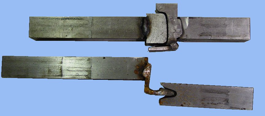
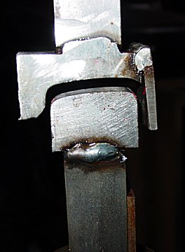
To fabricate these, a pair of dies were made for the Pullmax machine. The first die set was used to put in the crown on the top surface. The second was used to define the shape of the front of the moulding where it folds under. The dies were made of 3/4 inch square cold roll steel and 1 inch angle iron.
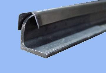
To begin fabricating the mouldings, a strip was cut from 22 ga. sheet metal. Two bends were made on the sheet metal brake. One would form the 90 degree angle on the back side, and the other would form the beginning of the front radius.
The resulting U shape was then run through the first die set on the Pullmax. This formed a slight crown into the top surface of the moulding.

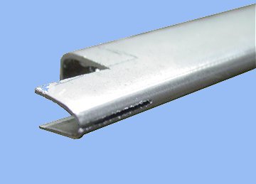
The next step was to continue bending over the front edge. This was done by hand using a hammer to form the bend over the bottom die of the second die set.

With the cross sectional shape of the moulding finished, it was time to start forming the rounded edges.
First, a section was removed from the end. The removed piece was smaller than what the finished moulding required. It will be opened up to the finial size later.
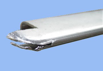
Next, a slot was cut along the center of the U shaped front edge. When forming this rounded corner, there is quite a bit of extra metal. It would be difficult to shrink this much metal in such a small area. The slit allows the top and bottom to be formed and the extra metal can simply be cut away.
Another forming die was made from a piece of 1 inch angle iron with the corners rounded to the proper radius. By inserting this into the moulding, the top and bottom of the curved edge can be hammered over the form to get the proper shape.

Once the top was formed over the form, the extra metal was removed so the top section did not extend beyond the centerline of the moulding. The extra metal was then removed from the bottom section and the bottom section worked over the form to provide the same shape.

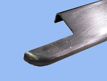
Once the top and bottom sections of the corner were formed, the slot was welded closed. Final shaping was done using a air grinder, files and sandpaper. The final step was to trim the opening on the ends to the proper size. The front moldings were then cut to length with an angle cut while the rear moldings had the same procedure for rounding the corner performed on the other side.

Note: The original mouldings had a series of countersunk holes to accomodate the oval head wood screws used to attach it to the car body. We were asked to provided these without those countersunk holes.