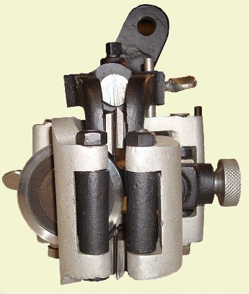
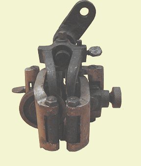
Newell Design Lower Blade Guide. The pin to allow the guide to pivot is held by the thumb screw at the top right.
| "Famous" No. 1 |
| 32" Band Saw |
Restoration of the Lower Blade Guide
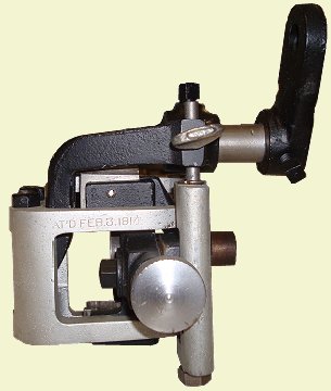
The lower blade guide on this saw has a patent date of Feb. 3, 1914 stamped onto one of the aluminun arms. A search of the patents issued on that date shows patent # was issued to Newel for a self aligning band saw blade guide. While the photos in the patent do not match this guide exactly, there are many similarities which indicate that the blade guides on this saw are of the Newell design. The Newel design blade guides were manufactured by the Automatic Saw Guide & Machine Co.
The main feature of the Newell guide is that it has the ability to pivot. For normal straight cutting, the rear of the guide is pinned in place allowing it to function as a standard guide. When cutting tight radius curves, the pin is removed. This allows the back portion of the guide to pivot to allow the blade to twist to accomodate the small radius.
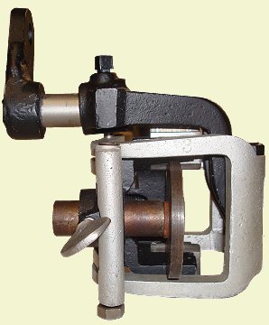
Newell Design Lower Blade Guide. The pin to allow the guide to pivot is held by the thumb screw at the top right.
The first step in restoring the lower blade guide was to blow out all of the sawdust which had collected in the guide. This was followed by a trip through the parts cleaner. The guide was then photographed in detail then carefully disassembled and inspected. The inspection reveiled several areas of wear which will need to be repaird.
Main body and Arms
The main body consists of two pieces. The main body holds two wear guides which rub against one side of the blade. A second adjustable piece contains the two guides for the other side of the blade. The adjustable piece is held in place with a bolt, and is adjusted using a knob. Both of these pieces were bead blasted, primed and painted. The wear blocks have some slight wear on them, however the wear is minimal and at this time it was decided to leave them as is. The two aluminum arms were also glass beaded. Since these are aluminum and were not painted originally, they were left natural.
Lower Guide Roller
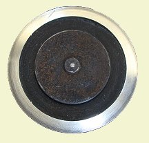
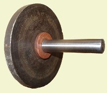
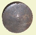
The lower guide roller consists of a 2 3/8" diameter cast roller swaged to a steel 3/8" diameter shaft. At some point the roller became stuck in the bushing, preventing it from turning freely. The blade wore a groove in the face of the roller. Also, the shaft is worn with a 0.009" taper.
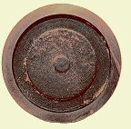 | 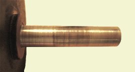 | |
| Grooves worn in the face of the roller. | Worn roller shaft |
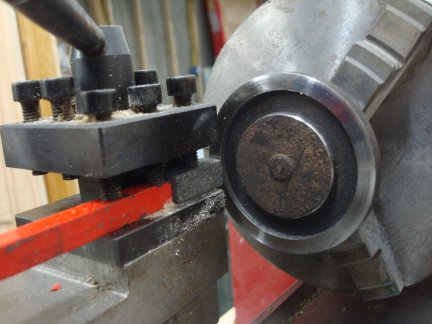
To remove the grooves from the face of the roller, the roller was chucked in a lathe. A grinding stone was pressed up against the face of the roller. After several seconds of grinding, the lathe was stopped, the roller removed and cooled in water, then remounted in the lathe and the process repeated. One the face of the roller was refinished, the shaft was then cleaned up. Just enough was removed from the shaft to remove the taper and get a smooth surface.
 |  |
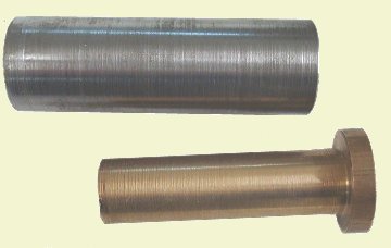
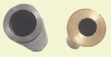
Lower Guide Roller Bushing
The bushing for the lower guide roller consists of a 3/4" diameter steel outer casing with a bronze bushing inside. The bushing is quite worn. There also seems to be no way to get oil into this bushing.
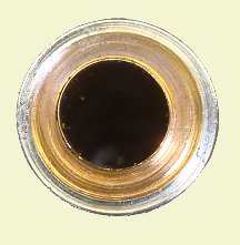
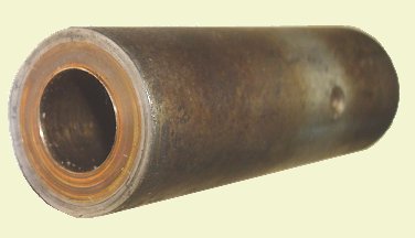
The solution here is to make a new housing and bushing. The housing is the same dimensions as the original. The hole in the housing is bored slightly longer than the inner bushing. The back of the housing was drilled and tapped to accept an oiler from a Model T Ford generator to allow oil to be added to lubricate the lower guide roller shaft.
A new bushing was made out of bearing bronze. The new bushing contains a shoulder on the outer edge so that the back of the roller rides on the bronze bushing instead of against the end of the steel housing.
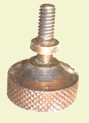
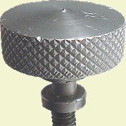
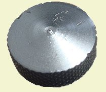
Adjustment Knob and Thumbscrews
There is one adjustment knob on this guide which is used to open and close the jaws of the guide. When inspected, this knob had the remains of nickel plating on it. Likewise, the thumbscrew which holds the guide to the mounting arm, and the thumbscrew which holds the locking pin in position were also found to have nickel plating on them. The restoration of these parts was actually quite simple. The parts were first glass beaded. A file was used to clean up the major damage areas, then another trip through the glass bead cabinet removed any small file marks. The adjustment knob was chucked in the lathe and spun while a brillo pad was held against it to polish it. The thumbscrews were simply polished by hand with the brillo pad.
The parts were plated using the brush plating kit sold by Caswell Plating. A gause strip is wrapped around a stainless wand. A small battery charger is connected with the + lead to the wand and the - lead to the part. The gause is then soaked in a Nickel Sulfate solution and rubbed against the part. In a few seconds, a layer of nickel is deposited on the part. The part is then washed off, and buffed with a metal polish.
Completed Lower Blade Guide
All of the remaining pieces were glass beaded, primed and painted in a semi-flat black paint. The blade guide was then reassembed.